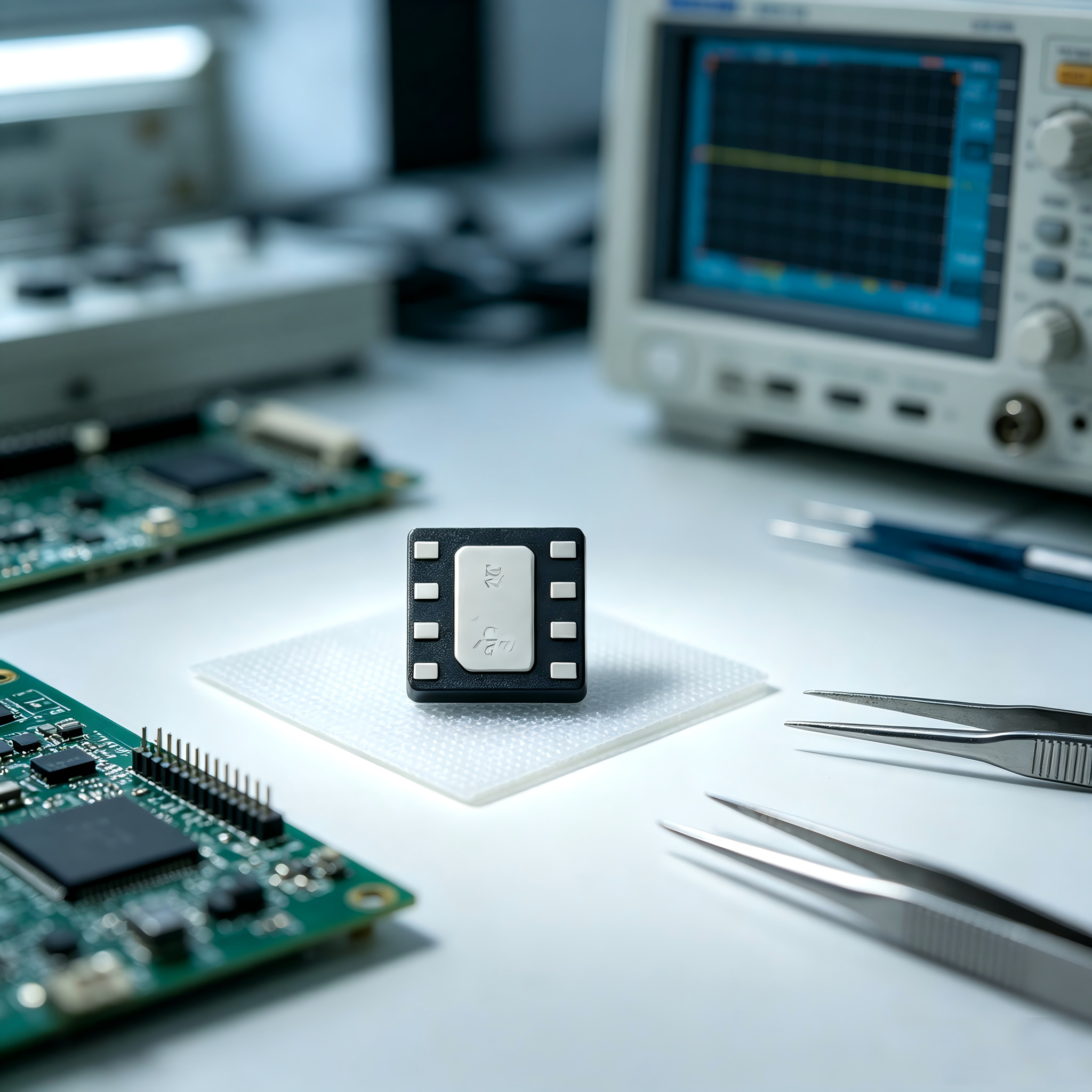
Upgraded Domestic 3D‑Hall: KunTaiXin KTH5502, Multi‑interface Absolute Angle Sensor
2026.08.28
16 次
KTH5502
KTH5502

—Next‑level Domestic 3D‑Hall—

CONNTEK KTH5502

Multi‑interface All‑in‑One Absolute‑Angle Sensing Solution

# Magnetic Angle Sensor # 3D Hall Sensor # Motor Control # Domestic Substitution # Magnetic Encoder

Traditional optical‑electrical encoders are highly susceptible to dust, vibration and temperature variations. They require zero‑point calibration upon power‑on and come with relatively large form factors. A growing number of motion‑control projects are shifting toward non‑contact magnetic angle‑sensing solutions.

Today, we introduce the CONNTEK KTH5502 Series, a flagship offering from Junmin Technology. This high‑precision 3D‑Hall magnetic angle sensor is built on vertical‑Hall technology. It achieves 0‑360° full‑range absolute‑position measurement on a single chip. Supporting multiple interfaces and housed in a compact package, it facilitates device miniaturization and domestic‑substitution upgrades.


Core Technology: Vertical‑Hall 3D Magnetic‑Field Sensing


The KTH5502 integrates X/Y‑axis vertical‑Hall elements and a Z‑axis horizontal‑Hall element internally to simultaneously acquire XYZ tri‑axial magnetic‑field signals. Combined with a 16‑bit ADC and hardware‑accelerated CORDIC calculation algorithm, it directly outputs the absolute angle of the XY‑plane. Complex trigonometric computations are offloaded from the MCU, easing the computing load of the main controller.

Compared with conventional planar‑Hall solutions, the vertical‑Hall architecture delivers superior orthogonal matching and lower offset. It provides stronger tolerance against magnet assembly eccentricity, yielding more stable and reliable angle output under assembly tolerance and vibration‑prone working conditions.


Key Performance‑Specs at a Glance

✅ Full‑range Angle Measurement: 0‑360° absolute‑angle output. Position can be read directly upon power‑on; homing is not required 

✅ Resolution: 16‑bit digital angle resolution. Typical integral non‑linearity ±1.0°, maximum ±2° 

✅ Wide Supply Voltage: 1.7V‑3.6V, compatible with lithium‑battery and 3.3V industrial systems 

✅ Wide Operating Temperature: ‑40℃ ~ +125℃, industrial‑grade temperature coverage 

✅ Power Consumption: Typical operating current 4‑6 mA 

✅ Maximum Rotational Speed: Supports continuous rotation up to 5000 RPM 

✅ AB Quadrature Encoding: Up to 1024 lines per revolution, capable of directly replacing incremental encoders 

✅ Two Package Options 

SOP‑8L: 5.0×4.0 mm, for general SMT mounting 

DFN‑8L: 2.0×2.0 mm ultra‑compact package, ideal for extremely space‑constrained applications

 Five Output Interfaces, One Chip for Most System Requirements


The biggest highlight of the KTH5502 lies in its exceptionally rich interface options. A single chip supports multiple output modes, which can be switched simply via the MODE pin to adapt to varying hardware resources of different MCUs:

  • I²C: Standard/Fast‑mode (100K‑400 kHz). The base version supports I²C address switching through the A0 pin, enabling multiple chips to share the same bus.

  • SPI: 3‑wire Mode 3, maximum 5 MHz clock rate with CRC8 data checksum to improve communication reliability under industrial conditions.

  • AB Quadrature Encoding: Push‑pull A/B‑phase output, programmable resolution from 12‑1024 lines, for direct connection to encoder interfaces.

  • PWM Output: Two configurable rates: 972 Hz (13‑bit) / 486 Hz (14‑bit), well‑suited for long‑distance transmission.

  • Analog Voltage Output (Standard‑line‑count variant): Output voltage varies linearly with angle and can be directly sampled by the MCU’s ADC.


Selection Notes:

  • Base model: OUT/A0 serves as I²C address‑select pin; analog output is unavailable.

  • Standard‑line‑count model: OUT/A0 is configured for analog voltage output; I²C address is fixed at 0x6A. Always check part‑number specifications in hardware design to avoid pin‑function misuse.


Rich Configuration Capabilities for Customized Project Requirements


The chip exposes multiple sets of registers and supports user‑side software parameter tuning:

✔ Angle Zero‑point Trimming: 16‑bit parameter to correct mechanical zero‑point deviation caused by installation 

✔ Gain and zero‑point trimming for analog output to calibrate analog‑output offset 

✔ ADC oversampling configuration to balance noise performance and response speed 

✔ Adjustable digital‑filter stages for magnetic‑field noise suppression 

✔ CM continuous‑measurement mode with configurable measurement interval, balancing refresh rate and power consumption


All registers support read‑modify‑write operations. Sample C‑code is provided in the appendix of the datasheet for quick‑start development.


Typical Application Scenarios


  • Motor Control: Closed‑loop position feedback for BLDC brushless motors and stepper motors

  • Robot Joints & Collaborative Robots: Joint‑angle detection

  • Gimbal Stabilizers & Hand‑held Stabilization Devices

  • Joysticks, Game Controllers, Industrial Smart Knobs and Control Panels

  • Valve Opening and Steering‑angle Position Detection

  • Direct replacement for traditional optoelectronic encoders, enabling cost‑reduction, miniaturization and maintenance‑free design


Magnet & PCB Design Guidelines (Must‑read for Pit Avoidance)


To achieve optimal chip performance, please observe the following hardware‑design requirements:

  • Magnet Recommendation: 2‑pole radially‑magnetized cylindrical magnet. Preferred dimension: φ6 mm, thickness 2.5 mm.

  • Air‑gap: 0.5‑2.0 mm between magnet surface and chip surface; 1 mm is recommended.

  • Alignment Requirement: Offset between magnet center and chip Hall‑sensing center shall be less than 0.3 mm.

  • Magnetic‑field Strength: In‑plane magnetic field at chip surface: 200‑1000 Gauss.

  • PCB Layout: Place 100 nF + 10 μF decoupling capacitors close to VDD‑GND. Minimize copper area around the sensor and keep away from inductors and strong magnetic interference sources.


Ordering Part‑Numbers at a Glance


  • SOP‑8L: KTH5502HVPSP8 (base 12‑line), multi‑line‑count variants: AB50 / 100 / 128 / 256 / 512 / 1024

  • DFN‑8L: KTH5502HVPDN8 (base 12‑line), line‑count variants ranging from AB50 to AB1024

  • Variants with different line counts suit various rotational‑speed scenarios. Pay attention to the maximum‑speed limit for high‑line‑count versions.

  • Featuring vertical‑Hall technology, full‑interface coverage, dual‑package options and industrial‑grade wide‑temperature range, the KTH5502 delivers a cost‑effective domestic solution for motor closed‑loop control and angular‑position detection. It is well‑worth adding to your component shortlist for both new‑project development and localization substitution of imported sensors.

秀米XIUMI

微信号丨189 2646 8515

官网丨www.junmintech.cn

点击蓝字,关注我们


Back to list