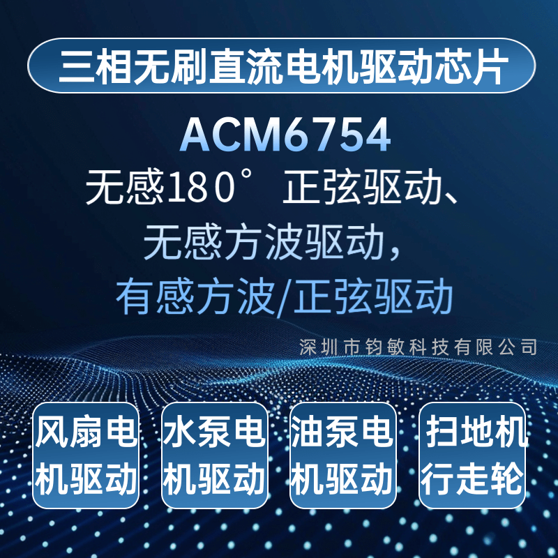

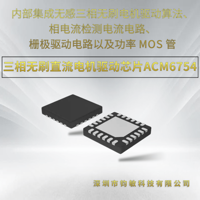


| Overview of ACM6754 ACM6754/55 is a three-phase brushless DC (BLDC) motor driver chip integrating sensorless three-phase BLDC motor driving algorithms, phase current detection circuits, gate driving circuits and power MOSFETs internally. It supports a maximum phase current of 5A. With its high integration and simplified peripheral circuitry, ACM6754/55 is ideally suited for three-phase BLDC motor driver applications requiring high power density, compact size and excellent noise suppression performance. ACM6754/55 supports multiple driving modes, including sensorless 180° sine wave driving, sensorless square wave driving, sensored square wave/sine wave driving (supported by ACM6755) and open-loop sine wave driving. Among these modes, the sensorless 180° sine wave driving effectively eliminates electromagnetic noise interference caused by high-order harmonics, while the sensored square wave/sine wave driving can cope with variable-load applications efficiently. ACM6754/55 enables smooth startup, acceleration and constant-speed operation of motors based on user-defined motor parameters. These parameters can be permanently configured via programming (hardware mode, programmed and burned into the internal EEPROM) or adjusted dynamically through I²C communication (software mode, parameter initialization or real-time control via I²C registers). ACM6754/55 provides multiple speed control methods, including external PWM duty cycle control, external analog voltage control, I²C register control and external PWM frequency control. ACM6754/55 is equipped with a variety of protection mechanisms to safeguard both the chip itself and the external motor connected to it. |
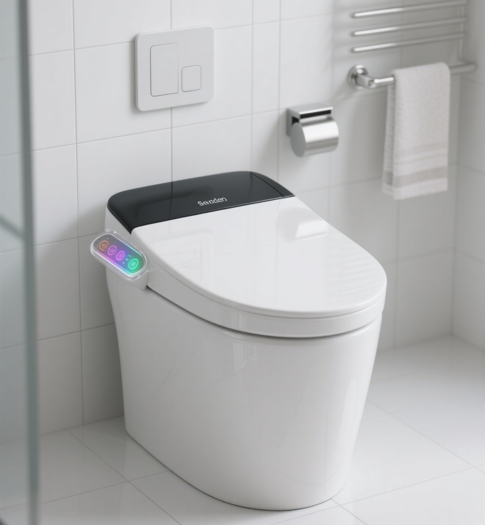
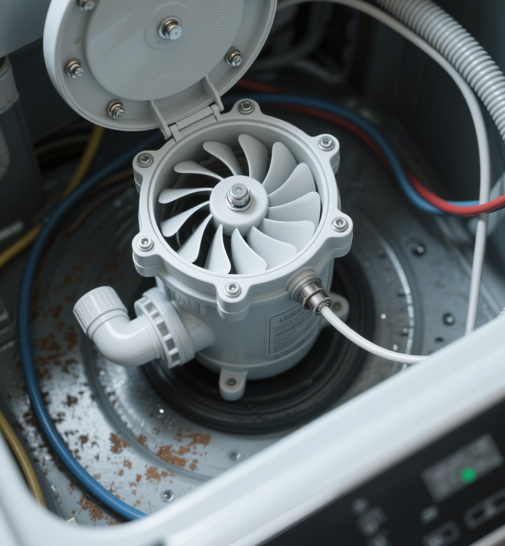
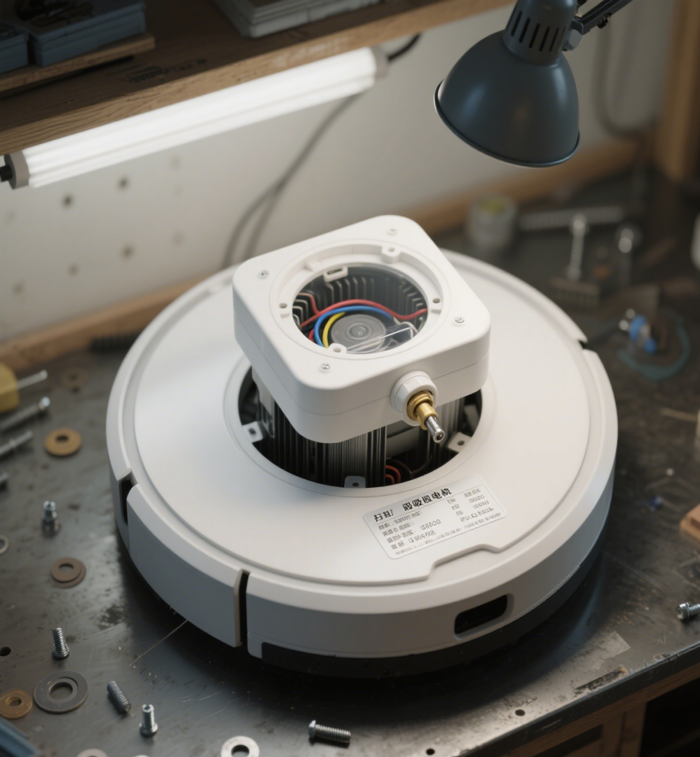
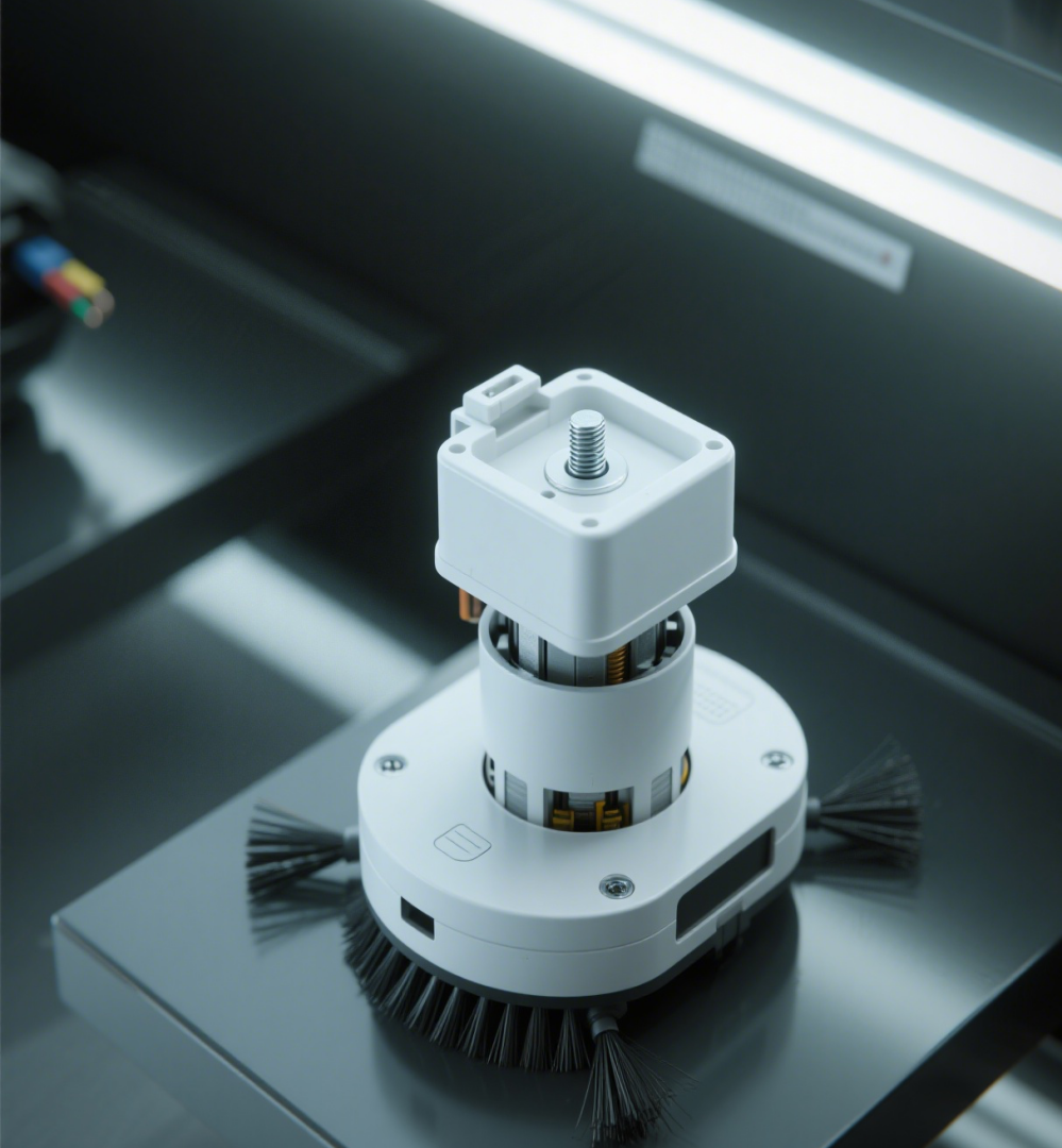
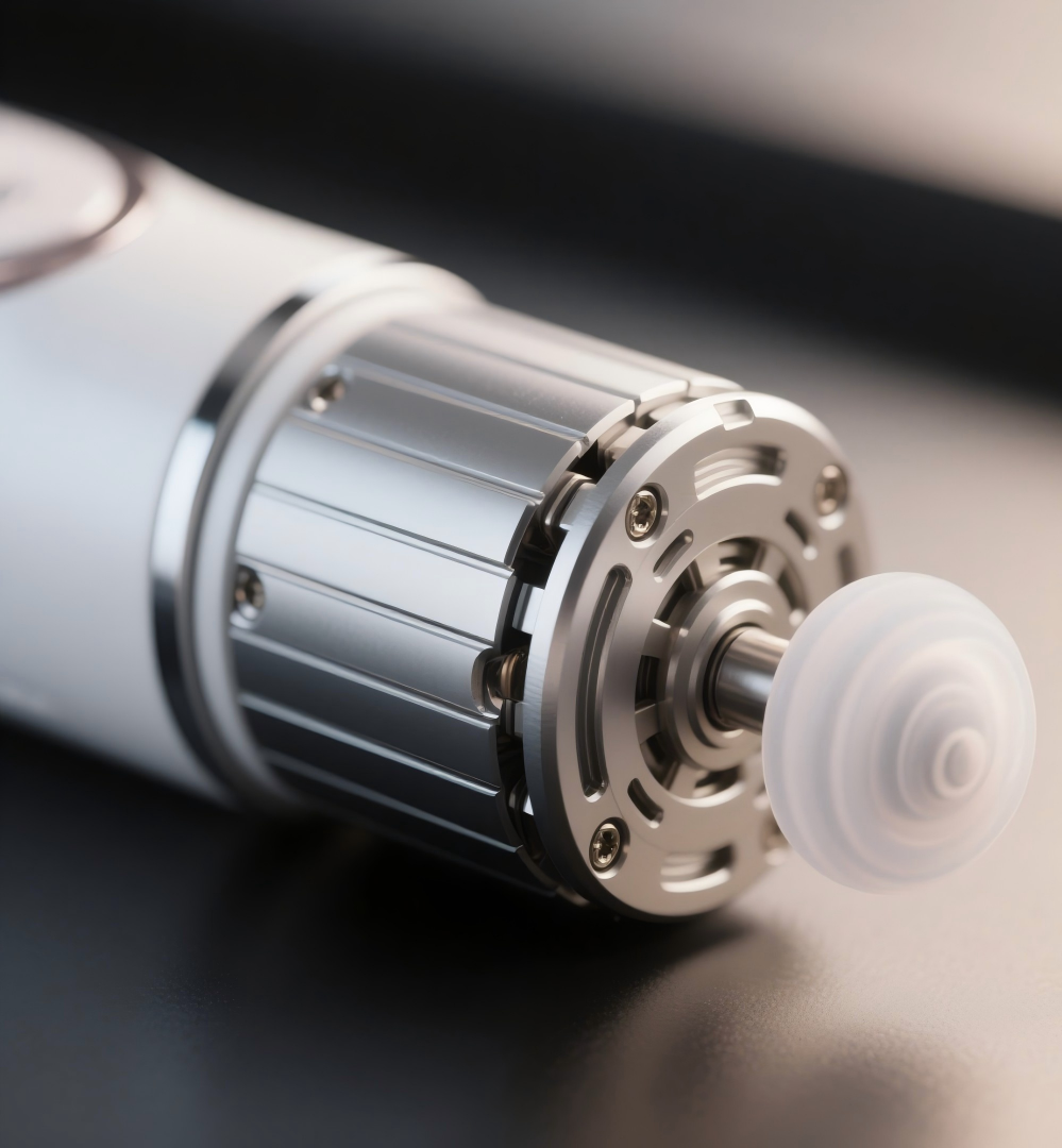
ACM6754 Pin Definitions and Pin Function Descriptions: | Applications of ACM6754:
|
Input Voltage Range: 5V - 28V
On-resistance (High-side + Low-side MOSFETs): 160mΩ, 5A Phase Current Capability
Supported Driving Modes: 180° sensorless sine wave driving (ultra-low noise), sensorless open-loop sine wave driving, and sensorless square wave driving. No external current-sensing resistors required, with flexible selection based on specific applications.
Hall Sensor-based Driving Support: 3-Hall square wave driving, 3-Hall sine wave driving, and 1-Hall sine wave driving
Built-in LDOs: 5V and 3.3V
FG Speed Indication Signal: Electrical cycle or mechanical cycle, with configurable division ratio
VCC Voltage Detection: I²C Reporting
Internal Junction Temperature: I²C Reporting
Real-time Phase Current: I²C Reporting
Forward/Reverse Control: External DIR pin or I²C register control
Brake Control
External BRAKE pin control
I²C interface: Brake control via register configuration
4 Flexible Speed Control Methods
Dedicated SPEED pin: Accepts external analog voltage for speed regulation
PWM duty cycle speed regulation
Clock signal speed regulation
I²C register speed regulation
Protection Functions
Overcurrent protection & motor lock protection
Overvoltage/undervoltage protection
Overtemperature protection
Voltage reverse polarity protection (overshoot prevention) mechanism
Water pump no-load protection mechanism
Quiescent Current (Standby Mode): 150μA, activated by setting I²C speed command to zero and external SPEED pin voltage to zero
Quiescent Current (Sleep Mode): 20μA, wake-up triggered by rising voltage of the external SPEED pin